
Description
Thermowells are pressure-tight receptacles that extend the life of a temperature sensor in environments where the sensor is not chemically compatible with the process media or the sensor does not have the mechanical strength to withstand the process flow or pressure. Thermowells also facilitate removing, changing, checking or replacing sensors without draining the process system. The use of standardized thermowells throughout a plant permits easy relocation of sensors.
Thermowell Design Factors
Material of Construction
Thermowell material must be chemically compatible with the process system and the temperature sensor. In most cases, thermowell selection is based on the corrosive conditions in the well environment. Sometimes the selection may be based solely on the mechanical strength needed to withstand operating pressure and process flow. Often a combination of factors must be considered. In addition to selecting the proper base material, coatings may be used to improve a thermowell’s resistance to abrasion or the chemical process.
The thermowell wall must be thin enough to minimize sensor error caused by thermal conduction and slow sensor response, but thick enough to withstand collapse from process pressure, erosion from abrasive media and bending from the process flow.
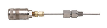
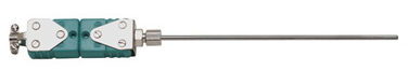
Spring-load mounting styles are recommended to ensure positive contact to maximize thermal transfer and minimize sensor vibration within a thermowell.
Insertion Length
The insertion length or ‘U’ length is the distance from the end of the well to the underside of the thermowell thread or other connection device. For maximum accuracy, this length must be long enough to permit the temperature sensor to be fully immersed in the media to be measured and minimize sensor error caused by thermal conduction, but short enough to withstand damage caused by process flow vibration. As a general rule of thumb, the thermowell should extend into the process a minimum of 10 times the sensor diameter or, in the case of RTDs,10 times the sensor diameter plus one inch. This should extend the sensor into the process between 1/3 and 1/2 the diameter of the process pipe. The insertion length must also take into consideration any dead length required to pass through walls, pipe fittings and insulation.
Velocity
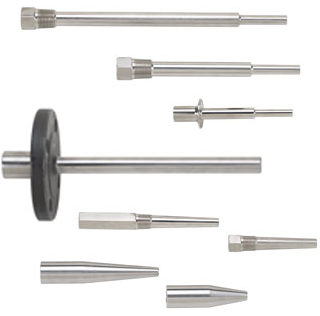
The most common cause of well failure is the vibration effect caused by fluid forming a turbulent wake as it flows past the well. This turbulence has a definite vibration frequency based on the diameter of the well and the velocity of the fluid. The well must have sufficient stiffness to ensure that the wake frequency will never equal the natural frequency of the well. If the natural frequency of the well coincides with the wake frequency, the well will potentially vibrate to destruction. To be in compliance with the ASME Performance Test Code, the thermowell should have a natural frequency a minimum of 125% of the wake frequency. Tapered shank wells (heavy duty – Type H) have a high strength-to-weight ratio with a resultant higher natural resonant frequency than the equivalent length straight shank well. Tapered shank wells are preferred for operation at higher fluid velocities.
Process Connection
Conax Technologies provides standardized wells in most of the common connection types, including threaded, flanged and socket weld types with standard bore sizes. Threaded wells are available in materials that can be readily welded. Flanged wells are manufactured by welding a bar stock well to the specified flange style. Doubled-welded construction reduces crevice corrosion and stress problems by ensuring that no open joints are exposed inside or outside the installation.
Bore Size
Selection of a standard bore size throughout the plant permits the use of several types of temperature measuring instruments in the same wells. Conax standard bore sizes fit most commonly used temperature sensing devices. Most applications use 0.260″ or 0.385″ diameter bores. This number represents the inside diameter of the well, expressed in thousandths of an inch.
Standard Manufacturing Practices
Conax thermowells are constructed to the following tolerances/descriptions:
| Item | Tolerance/Description |
| Lengths | ±1/16″ on lengths 12″ or less ±1/8″ on lengths over 12″ |
| O.D. Tolerances | ±0.015 |
| Bore I.D. | +0.005 –0.003 |
| End Thickness | 1/4″ ±1/16″ |
| Concentricity of Bore to O.D. | ±10% of minimum wall thickness |
| Wetted Surfaces Finish | 16-32 Ra is standard. Special finishes are available on request. |
| Process Connection Thread | In compliance with ANSI BI.20.1-92. Thread specifications vary with the process connection size. |
| Instrument Connection | 1/2″-14 NPT standard, 1/2″-14 NPSM optional♠ |
| End of Wells | Break corners, no burrs |
| Lagging Extension | Hex on threaded wells (or wrench flats where applicable) |
| Stamping | Type of material standard; customer name and heat or tag number if required. |
| Flanges | Made in accordance with ANSI B16.5. Raised face is serrated 125/250 RMS STD |
| Welding | Full penetration welds are standard on 300 lb. and up |
♠ Pending availability, NPSM instrument connection may be substituted for NPT.
Thermowell Catalog Descriptions
The following format is used when ordering thermowells. When ordering a thermowell by itself, the initials ‘TW’ precede the description. When ordering a thermowell as part of an assembly, the thermowell description immediately follows the mounting style designation, replacing the sensor active length.
Pipewell
Conax also offers protection tubes in a variety of types and materials. Protection tubes are intended for use in applications where the tube will not be exposed to high pressure of fluid velocities. Pipewells, made from Schedule 40, 80 or 160 pipe, are the most commonly used form of protection tube. Mounting is generally achieved through a flange or threaded bushing welded to the pipe.